


Polyurethane Grouting Hole Size and Injection Patterns: Minimizing Surface Impact
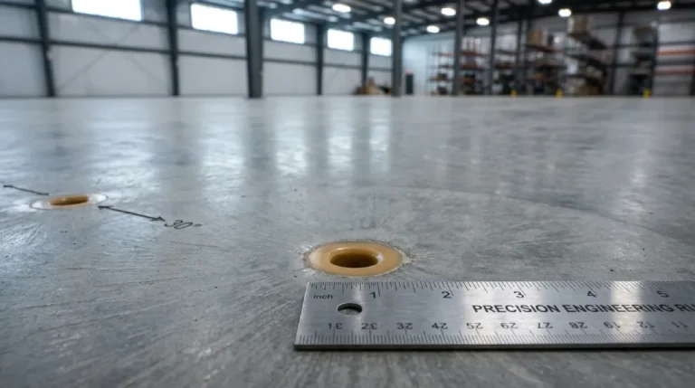
Modern polyurethane grouting on commercial and industrial slabs uses 5/8-inch diameter ports drilled at 24 to 48-inch spacing in engineered patterns (linear, grid, perimeter, or staggered) selected to match the documented void geometry. The combination of small port diameter, optimized spacing, and proper port finishing produces a rehabilitation that is essentially undetectable on the finished slab surface. Compared to traditional mudjacking, which uses 1.5 to 3-inch ports with limited surface restoration, polyurethane grouting reduces visible surface impact by more than 90 percent while delivering equivalent or superior structural performance.
When facility owners and specifying engineers evaluate polyurethane grouting, surface impact is often a secondary concern (cost, downtime, and durability lead the conversation), but it becomes a primary concern late in the project when the actual injection pattern is reviewed against the owner's aesthetic, operational, and cleanliness requirements. Modern injection patterns and port sizes are designed specifically to minimize this impact, and the difference between a contractor who optimizes for surface restoration and one who does not is visible long after the rehabilitation is complete.
This article presents the engineering of port size and injection patterns for commercial and industrial polyurethane grouting work. The audience is specifying engineers, facility managers, project architects, and owners evaluating rehabilitation methods where surface impact matters. Every parameter and recommendation is advisory and project-specific; final port size, pattern selection, and finishing approach must be validated by the engineer of record and matched to the project specification.
Why Port Size and Pattern Matter
For some applications, port size and injection pattern are technical details that do not affect the procurement decision. For others, they are the procurement decision. A polished concrete warehouse floor in a tenant showroom, a healthcare facility corridor, a food processing slab, a museum gallery, or a high-visibility loading dock all impose surface impact constraints that drive the selection of method and contractor.
A contractor who treats port pattern and finishing as an afterthought delivers a rehabilitation that succeeds structurally but is permanently visible on the slab surface. The owner who selected polyurethane grouting in part for its low surface impact may experience a finished result that does not match the expectation. A contractor who treats port pattern and finishing as engineering decisions delivers a rehabilitation that is essentially invisible on the finished surface, matching the value proposition that justified the method selection.
Polyurethane grouting services on commercial and industrial slabs are designed for surface-impact minimization as a default operating standard, not as a premium upgrade. The discipline behind that standard is the engineering content of this article.
Standard Port Diameter for Commercial and Industrial Work
The standard port diameter for modern polyurethane grouting on commercial and industrial slabs is 5/8 inch (0.625 inch, approximately 16 mm). This dimension is the result of optimization across several engineering constraints:
- Injection fitting compatibility: Standard two-component polyurethane injection guns use fittings that mate cleanly with 5/8-inch ports without flow restriction or back-pressure leakage.
- Material flow performance: The 5/8-inch port allows sufficient flow rate of the mixed two-component resin to fill voids efficiently while still controlling injection pressure within manageable ranges.
- Slab structural impact: A 5/8-inch port in a typical commercial slab (6 to 12 inches thick with structural reinforcement) is a negligible structural penetration. The port footprint is approximately 0.31 square inch, less than 0.05 percent of the surrounding slab area within a typical spacing.
- Drilling efficiency: The 5/8-inch port is efficiently drilled with standard handheld or wheeled rotary equipment in 30 to 90 seconds per port depending on slab condition.
- Surface restoration practicality: The 5/8-inch port can be cleanly finished with flush-cut foam trim plus color-matched non-shrink grout to produce a surface that is essentially undetectable.
Smaller-diameter ports (3/8 inch, 1/2 inch) are used in specialized applications where reduced surface impact is required and the corresponding constraints on flow rate and injection pressure can be managed. Larger-diameter ports (3/4 inch, 1 inch) are used where deeper substrate access is required, where larger void volumes require accelerated flow rates, or where specialized injection fittings demand a larger port.
For polyurethane foam injection on standard commercial industrial scopes, the 5/8-inch port is the default and the engineer of record need not request a non-default specification unless project-specific conditions require it.
Comparison: Polyurethane Ports vs. Traditional Mudjacking Ports
Mudjacking, the cementitious slurry-based slab lifting method that preceded polyurethane in widespread commercial use, requires substantially larger ports to accommodate the heavy slurry material flow. Comparison:
| Method | Standard Port Diameter | Typical Port Spacing | Surface Restoration | Visible Impact After Finishing |
| Polyurethane grouting | 5/8 inch | 24 to 48 inches | Flush-cut foam, color-matched grout | Essentially invisible |
| Mudjacking (cement slurry) | 1.5 to 3 inches | 36 to 60 inches | Cement patch (often visible) | Visible surface pattern |
| Traditional cementitious injection | 1 to 1.5 inches | 24 to 36 inches | Cement patch (visible) | Visible surface pattern |
| Cellular grouting | 1 to 2 inches | 24 to 48 inches | Concrete patch (visible) | Visible surface pattern |
The surface-impact differential is the primary reason polyurethane has displaced mudjacking in most commercial and industrial applications. For owners where surface appearance matters (showroom floors, healthcare facilities, food processing, polished concrete commercial spaces), the choice is functionally one-sided.
Four Standard Injection Patterns
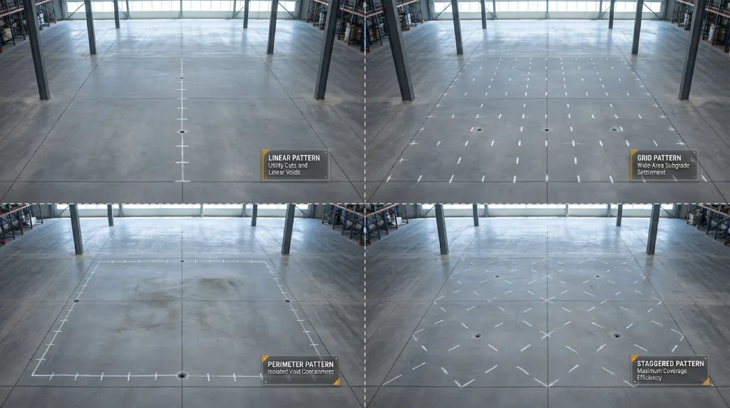
Port pattern selection matches the documented void geometry. Four standard patterns cover the majority of commercial application scenarios; engineered hybrid patterns adapt to atypical conditions.
Pattern 1: Linear
A linear pattern places ports along a single line at uniform spacing. The line follows the documented void axis (a utility cut trench, a backwall edge, a drainage washout path).
Best use cases:
- Utility cut settlement along a buried pipe trench
- Bridge approach slab settlement at the backwall
- Drainage washout along a curb or gutter line
- Linear void fills along structural edges
Typical spacing: 24 to 36 inches.
Surface impact: Single linear pattern is the lowest surface-impact pattern because all ports are aligned and minimal slab area is affected.
Pattern 2: Grid
A grid pattern places ports in a regular rectangular array across a documented void area. The grid spacing is uniform in both directions.
Best use cases:
- Wide-area subgrade voids beneath warehouse floors
- Fill consolidation settlement under freight corridors
- Large void fills under industrial slabs
- Comprehensive lifting of broadly settled slab sections
Typical spacing: 36 to 48 inches in each direction.
Surface impact: Grid produces visible port pattern if not finished carefully; with proper color-matched finishing, the grid is essentially invisible against industrial concrete texture.
Pattern 3: Perimeter
A perimeter pattern places ports around the boundary of a documented void zone, with the interior of the void filled by material migration from the perimeter ports.
Best use cases:
- Isolated void containment where the void boundary is well-defined
- Settlement around manhole frames and utility structures
- Localized void filling beneath equipment pads
- Containment around features that cannot be drilled (sensitive equipment, embedded fixtures)
Typical spacing: 24 to 36 inches along the perimeter.
Surface impact: Perimeter pattern minimizes interior surface impact since only the boundary is drilled.
Pattern 4: Staggered
A staggered pattern places ports in offset rows, with each row's ports positioned between the ports of the adjacent row, producing a diamond-grid effect. This pattern delivers more uniform material distribution per square foot than a regular grid.
Best use cases:
- Irregular void geometries that do not follow linear or grid alignment
- Slabs requiring maximum coverage efficiency
- Wide-area lifting with structural reinforcement constraints
- Applications where overlap between port influence zones is desired
Typical spacing: 36 inches between ports within a row, 30 inches between rows.
Surface impact: Staggered pattern produces a visible diamond pattern if unfinished; with proper finishing, this is no more visible than a grid.
How to Select the Right Pattern
Pattern selection follows the documented void geometry rather than contractor preference. A qualified specialty grouting contractor reviews the pre-injection investigation (GPR, boroscope, elevation survey) and proposes a pattern that fits the documented conditions. The engineer of record validates the selection before drilling begins.
| Documented Void Geometry | Recommended Pattern | Rationale |
| Linear void following utility line or backwall | Linear | Matches void axis, minimum port count |
| Wide-area subgrade voiding | Grid or staggered | Uniform coverage with appropriate spacing |
| Isolated localized void with defined boundary | Perimeter | Contains the void with minimal interior drilling |
| Irregular void with complex boundary | Staggered or hybrid | Maximum coverage efficiency for complex shapes |
| Settlement around fixed feature (manhole, drain inlet) | Perimeter | Avoids drilling through fixed structures |
| Drainage washout along a path | Linear | Follows the washout axis |
When void geometry is ambiguous or extends across multiple documented zones, a hybrid pattern combining elements from two or more standard patterns is appropriate. The hybrid is documented in the QA/QC submittal so the engineer of record can review the rationale.
Port Finishing and Surface Restoration
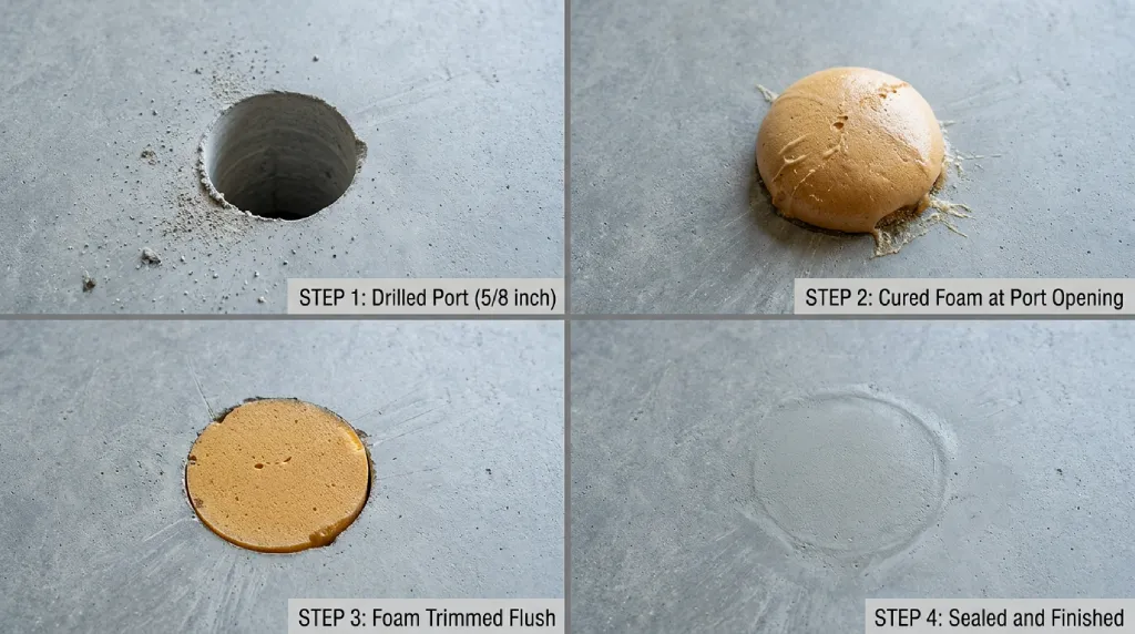
Port finishing is the operational step that converts a structurally complete injection into an aesthetically acceptable rehabilitation. The sequence is:
- Cured foam trim. After polyurethane reaches tack-free and full cure, the foam at the port opening (typically protruding 1/8 to 1/4 inch above the slab) is trimmed flush with the slab surface using a sharp blade or rotary trimmer.
- Port cleaning. The trimmed port is cleaned of foam dust and any residual material with shop-vac or compressed air, leaving a clean cavity for finishing material.
- Sealing. The cleaned port is filled with non-shrink grout (cement-based or epoxy-based depending on project specification) selected for color and texture match to the surrounding slab.
- Finishing. The applied finishing material is troweled or finished to match the surrounding slab surface texture (broom finish, troweled smooth, polished, exposed aggregate, etc.).
- Cure of finishing material. The non-shrink grout cures per its product specification (typically 1 to 24 hours for cement-based, 30 minutes to 2 hours for epoxy-based).
Color matching is the most important finishing variable. For polished concrete floors, healthcare facilities, food processing slabs, and other high-visibility applications, the finishing material color must match the existing slab. A qualified contractor maintains a color-matching capability with multiple color additives available on-site to mix to the exact slab color.
For industrial slabs where surface appearance is less critical (warehouse floors with painted lines, utility floors, mechanical room slabs), a standard non-shrink grout in a neutral gray is typically acceptable.
Special Considerations for High-Visibility Applications
Several application categories impose stricter surface-impact requirements:
- Polished concrete commercial floors: Finishing must preserve the polished appearance. Specialized polishable epoxy fillers or color-matched specialty grouts are specified, with finishing by a flatwork polisher after material cure.
- Food processing slabs: Finishing material must be food-grade or food-contact compliant. NSF-certified epoxy fillers are commonly specified. Sanitation protocols apply throughout the work.
- Healthcare facility floors: Antimicrobial or hospital-grade finishing materials may be specified. Coordination with infection control is standard.
- Museum and gallery floors: Aesthetic match is the highest priority. Sample finishing and approval before bulk application is common.
- Showroom or tenant-facing slabs: Owner aesthetic standards govern. Pre-construction mockup and approval is recommended.
For each of these applications, the void fill grouting or lifting scope is augmented by specialized finishing protocols and materials documented in the project specification.
Standard Port Spacing Reference
Port spacing is the second key variable after diameter. The standards below cover typical commercial and industrial work; project-specific conditions may require tighter or looser spacing.
| Application Type | Typical Port Spacing | Notes |
| Wide-area lifting (warehouse floor) | 36 to 48 inches | Grid or staggered pattern |
| Bridge approach slab | 24 to 36 inches | Linear at backwall, grid in transition |
| Loading dock approach | 24 to 36 inches | Linear at edge, grid in body |
| Utility cut settlement | 24 to 30 inches | Linear along cut |
| Manhole frame settlement | 24 to 30 inches | Perimeter around frame |
| Localized void fill | 24 to 36 inches | Perimeter or grid as appropriate |
| Drainage washout repair | 24 to 30 inches | Linear along washout path |
| Edge void fill (curb, structural edge) | 24 to 30 inches | Linear along edge |
Tighter spacing produces more uniform material distribution and is appropriate for thin slabs or where lift tolerance is tight. Wider spacing reduces port count and total surface impact but requires careful injection volume control to ensure complete void fill.
Port Depth Determination
Port depth is set by the depth of the documented void or the depth of the substrate that the contractor must reach. Standard approaches:
- Through-slab ports: Drilled completely through the slab to reach the subgrade directly beneath. Standard for wide-area lifting and void fill.
- Partial-depth ports: Drilled to a specified depth less than the full slab thickness, used when the rehabilitation targets the slab-to-subbase interface specifically.
- Multi-depth ports: A single port location drilled to multiple depths in stages for layered void fill or staged lift.
Port depth is recorded in the daily injection log with the corresponding void depth observed at injection. Pre-drilled depth verification with a depth gauge confirms the port reached the intended substrate before injection begins.
Operational and Safety Considerations During Drilling
The drilling phase produces concrete dust, vibration, and noise. Standard controls:
- Dust suppression: Shop-vac equipment or wet drilling captures fugitive dust at the source per OSHA respirable crystalline silica standards.
- Vibration management: Standard rotary or rotary-hammer equipment is used at controlled feed rates to minimize vibration transfer to sensitive adjacent operations.
- Noise control: Drilling noise is comparable to a standard rotary hammer at close range, dropping rapidly with distance. Hearing protection is required for crew within the work zone; adjacent operations are typically not affected beyond the immediate drilling phase. The Occupational Safety and Health Administration provides specific guidance through the OSHA Crystalline Silica Standard for dust control in concrete drilling work.
- Operational clearance: Drilling is staged to allow continued adjacent operations where possible; full work area isolation is required only when active drilling presents a direct safety conflict.
The drilling phase is typically the highest-impact operational moment of a polyurethane grouting project. After drilling, the injection phase is quiet, the material handling is contained, and the work proceeds with minimal operational disturbance.
Key Takeaways
- Standard polyurethane grouting port diameter on commercial and industrial work is 5/8 inch, drilled with low-impact rotary or rotary-hammer equipment.
- Port spacing typically ranges from 24 to 48 inches depending on void geometry, slab structural span, and material flow characteristics.
- Four standard injection patterns (linear, grid, perimeter, staggered) cover the majority of commercial application scenarios.
- Surface restoration of each port through flush-cut foam trim and color-matched non-shrink grout produces an essentially invisible final repair.
- Compared to traditional mudjacking ports (1.5 to 3 inch diameter), polyurethane grouting reduces visible surface impact by more than 90 percent.
- Port pattern selection is governed by void documentation, slab structural conditions, and operational constraints rather than by contractor preference.
- Every parameter in this article is advisory and project-specific. Final pattern and port specification must be validated by the engineer of record.
Frequently Asked Questions
What is the typical hole size for polyurethane grouting on commercial slabs?
Standard polyurethane grouting port diameter on commercial and industrial slabs is 5/8 inch (0.625 inch). This dimension balances injection fitting compatibility, material flow performance, slab structural impact, drilling efficiency, and surface restoration practicality. The 5/8-inch port represents less than 0.05 percent of the surrounding slab area at typical 24 to 48-inch spacing. Smaller diameters (3/8 inch, 1/2 inch) are used in specialized applications where reduced surface impact is critical; larger diameters (3/4 inch, 1 inch) are used where deeper substrate access or accelerated flow is required.
How does polyurethane grouting port size compare to mudjacking?
Polyurethane grouting uses 5/8-inch diameter ports. Mudjacking, the cementitious slurry-based predecessor method, uses 1.5 to 3-inch diameter ports to accommodate the heavy slurry material flow. The size differential produces a roughly 90 percent reduction in visible surface impact when polyurethane is used. Polyurethane port spacing is typically 24 to 48 inches; mudjacking spacing is typically 36 to 60 inches. The combination of smaller ports and finishing capability is the primary reason polyurethane has displaced mudjacking in most commercial and industrial applications.
How is the injection port pattern selected for a polyurethane grouting project?
Pattern selection follows the documented void geometry rather than contractor preference. Four standard patterns cover most commercial application scenarios. Linear pattern follows the void axis (utility cuts, backwall edges, drainage washout paths). Grid pattern provides uniform coverage of wide-area voids. Perimeter pattern contains isolated voids with defined boundaries (settlement around manholes, equipment pads). Staggered pattern provides maximum coverage efficiency on irregular voids. A qualified contractor reviews the pre-injection investigation (GPR, boroscope, elevation survey) and proposes a pattern that fits the documented conditions; the engineer of record validates the selection before drilling begins.
Can polyurethane grouting injection ports be made invisible after the work is complete?
Effectively, yes. After cured foam is trimmed flush with the slab surface, each port is filled with non-shrink grout color-matched to the surrounding slab and finished to match the existing surface texture. On industrial concrete with a standard troweled finish, the finished ports are detectable only by close inspection. On polished concrete, healthcare facility floors, food processing slabs, and other high-visibility surfaces, specialized finishing materials (polishable epoxy, NSF-certified materials, color-matched specialty grouts) deliver an effectively invisible final surface. The level of finishing detail is specified during the pre-construction phase to match owner expectations.
What spacing is used between polyurethane grouting injection ports?
Standard port spacing for commercial and industrial work ranges from 24 to 48 inches depending on application type, void geometry, slab structural span, and material flow characteristics. Wide-area lifting on warehouse floors typically uses 36 to 48-inch spacing. Bridge approach slabs and loading dock approaches typically use 24 to 36-inch spacing. Utility cut settlement, manhole frame settlement, and edge void fill typically use 24 to 30-inch spacing. Tighter spacing produces more uniform material distribution; wider spacing reduces port count and surface impact. Project-specific spacing is determined by the engineer of record against the documented void conditions.
Will the injection ports weaken the structural integrity of my slab?
When properly executed, 5/8-inch ports drilled at standard spacing produce negligible structural impact on the slab. A typical industrial slab is 6 to 12 inches thick with structural reinforcement; a 5/8-inch port is a small penetration that does not compromise the slab's load capacity or structural performance. Port locations are selected to avoid critical reinforcement and to maintain adequate edge clearance from joints and structural features. After port finishing with non-shrink grout, the port location is effectively continuous with the surrounding slab. A qualified contractor maintains drilling protocols that protect existing reinforcement and confirms structural compatibility with the engineer of record during the submittal phase.
How are polyurethane grouting ports finished to match the surrounding slab?
Port finishing follows a five-step sequence: trim cured polyurethane foam flush with the slab surface using a sharp blade or rotary trimmer, clean the trimmed port of foam dust and residual material, fill the cleaned port with non-shrink grout (cement-based or epoxy-based depending on project specification) selected for color and texture match, finish the applied material to match the surrounding slab surface texture, and allow the finishing material to cure per its product specification. Color matching uses multiple color additives mixed on-site to match the exact slab color. For polished concrete or high-visibility applications, specialized polishable fillers and post-cure polishing produce an effectively invisible finish.
Are smaller-diameter ports available for sensitive surface applications?
Yes. Specialized 3/8-inch and 1/2-inch ports are available for applications where reduced surface impact is required and the corresponding constraints on flow rate and injection pressure can be managed. These smaller ports are used on polished concrete in retail environments, healthcare facility corridors, museum floors, and other high-visibility surfaces where the standard 5/8-inch port would be detectable even after finishing. The smaller-port specification is documented in the submittal package and validated by the engineer of record. Note that smaller ports require corresponding adjustments to injection equipment, material flow control, and lift staging; these are managed by the contractor as part of the engineered scope.
Can polyurethane grouting be used on polished concrete commercial floors?
Yes, with specialized finishing protocols. For polished concrete commercial floors, smaller-diameter ports (3/8 inch or 1/2 inch) are commonly specified, the injection pattern is selected for minimum surface impact, and the port finishing uses polishable epoxy fillers or specialty color-matched grouts followed by post-cure polishing to restore the polished surface appearance. Pre-construction mockup and owner approval of the finishing approach is standard. The combination of small ports, careful pattern, and specialized finishing produces a rehabilitation that does not visibly disturb the polished surface, even on showroom and tenant-facing applications.
How long does the port finishing process take per port?
Port finishing is performed after the polyurethane grout reaches tack-free and the lift is verified. Each port requires approximately 1 to 3 minutes for cured foam trimming, cleaning, and grout application; finishing material cure adds 30 minutes to 24 hours depending on material specification. For a 100-port project, total finishing time is typically 3 to 8 hours of crew time spread across the cure period. Polished concrete and other specialty applications may add 1 to 2 hours per 100 ports for additional finishing detail. To scope a polyurethane grouting project with surface-impact requirements specific to your facility, schedule an estimate with Superior Grouting.
Conclusion
Polyurethane grouting port size and injection pattern are engineering decisions, not afterthoughts. Modern commercial and industrial work uses 5/8-inch diameter ports drilled at 24 to 48-inch spacing in one of four standard patterns (linear, grid, perimeter, staggered) selected to match the documented void geometry. Port finishing using flush-cut foam trim and color-matched non-shrink grout produces a surface restoration that is essentially undetectable on the finished slab. Compared to traditional mudjacking with 1.5 to 3-inch ports and limited surface restoration, polyurethane grouting reduces visible surface impact by more than 90 percent while delivering equivalent or superior structural performance. For high-visibility applications including polished concrete, healthcare facilities, food processing slabs, and showroom floors, specialized small-diameter ports and finishing protocols extend the method's surface-impact advantage further. Every parameter in this article is advisory and project-specific; final port specification, pattern selection, and finishing approach must be validated by the engineer of record. To scope polyurethane grouting work where surface impact is a critical specification on a commercial or industrial facility in Texas or Louisiana, contact Superior Grouting.