


Bridge Approach Slab Repair with Polyurethane Grouting: Eliminating the Bump at the End of the Bridge
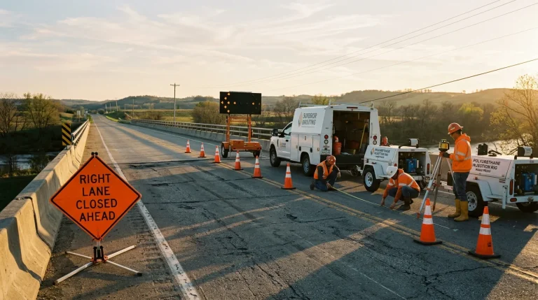
Bridge approach slab settlement (the "bump at the end of the bridge") is caused by void development beneath the slab from drainage washout, embankment fill consolidation, and loss of support behind the abutment backwall. Polyurethane grouting fills voids, lifts the slab to the design profile within specified tolerances, and restores rideability without lane-long closures or slab removal, typically in a single work window of 4 to 8 hours per bay.
The bump at the end of the bridge is one of the most recognizable defects in highway infrastructure. Drivers feel it every time they cross from pavement to bridge deck and back. DOT maintenance budgets track it as a recurring line item. For engineers responsible for bridge approach slabs, it is both a predictable failure mode and a persistent maintenance problem, caused not by the bridge itself but by the settling soil beneath the transition from pavement to structure.
This article examines the failure mechanism, the conditions that produce it, and the role of polyurethane foam injection as a remediation method aligned with DOT specifications. It is written for bridge owners, DOT engineers, design consultants, and general contractors evaluating approach slab remediation options. Every parameter, spec reference, and procedure below is advisory. Final design and execution must be validated by the engineer of record against site-specific conditions and the governing owner specification before work proceeds.
What Causes the Bump at the End of the Bridge

The bump is a settlement differential. The bridge structure itself rests on deep foundations (piles, drilled shafts, or spread footings) that settle negligibly under service loads. The approach slab, immediately adjacent to the abutment, rests on compacted embankment fill that continues to consolidate over time. The result is a progressive elevation mismatch between the rigid bridge deck and the approach pavement, concentrated at the backwall interface.
Three distinct mechanisms contribute to the differential, usually operating together rather than in isolation. Understanding each is the precondition to specifying the right remediation scope.
Mechanism 1: Drainage washout behind the backwall
Surface water enters joints between the approach slab and the bridge deck, penetrates the backwall drainage system, and (when the drainage system is inadequate, clogged, or compromised) washes fine soil from the fill directly beneath the approach slab. Over successive wet seasons, the washout creates progressively larger voids at the backwall corner. The approach slab, designed as a simply supported span between the bridge seat and the downstream sleeper slab, loses its uniform support and begins to deflect into the void. This is typically the dominant mechanism in regions with heavy rainfall, freeze-thaw cycles, or compromised pavement joint integrity. Once established, washout is progressive: each storm event enlarges the void, and the bump grows. Void fill grouting is the targeted remediation class for this condition.
Mechanism 2: Embankment fill consolidation
Embankment fill compacted during bridge construction continues to consolidate under its own weight and under repeated traffic loading. Even with modern compaction specifications, some post-construction settlement is expected, typically 1 to 4 inches over the first several years, with secondary compression continuing more slowly thereafter. Approach slabs are designed to span across the expected settlement, but the design assumption has a limit. When the embankment fill was placed with marginal compaction, when subgrade soils beneath the embankment continue to consolidate, or when groundwater conditions have accelerated settlement, the slab can exceed its design span and begin to bridge across a widening void. The distress correlates with post-construction age and loading history rather than with a single event.
Mechanism 3: Differential settlement at the rigid-compressible transition
The third mechanism is the geometry itself. A rigid bridge on deep foundations does not settle. The adjacent earthwork does. Even a well-executed approach slab transition experiences measurable differential settlement over the service life of the bridge because the foundations of the two systems respond differently to load. The cumulative effect appears at the approach slab as a concentrated elevation discontinuity at the backwall and a subtler grade change along the transition length.
| Mechanism | Primary Driver | Field Indicator |
| Drainage washout | Water entering joints, washing fines from beneath slab | Void concentrated at backwall corner; grows with storm events |
| Embankment fill consolidation | Compaction below specification or ongoing subgrade settlement | Progressive settlement correlated with age and loading |
| Differential rigid-compressible transition | Geometry of deep-founded bridge vs compressible earthwork | Concentrated elevation discontinuity at the backwall |
Why Polyurethane Grouting Fits the Failure Mode
Several remediation options exist for addressing slab settlement. Each addresses some of the failure mechanisms, and none addresses all of them perfectly. Polyurethane grouting addresses a specific defect profile common in the field: a structurally sound approach slab, voids beneath the slab at the backwall or in the transition zone, and a need to restore profile without extended lane closures.
The key engineering properties that make polyurethane grouting well-suited for bridge approach slab repair are summarized in the matrix below. Each property maps to a field constraint that most alternatives fail to satisfy simultaneously.
Table 2: Engineering Properties for Bridge Approach Slab Application
| Property | Why It Matters for Approach Slab Work | Typical Value | Reference |
| Low injected weight | Does not reconsolidate weak embankment fill | 2 to 5 pcf cured | Product TDS |
| Rapid cure | Short lane closures; same-shift return-to-service | Tack-free 5 to 15 min | Product TDS |
| Controlled expansion | Precise lift within 1/4-inch tolerance possible | Multi-stage lift per port | Engineer of record |
| Small port footprint | Minimal surface damage; no slab removal | 5/8 inch typical | Superior Grouting procedure |
| Closed-cell structure | Resists ongoing washout in drainage-compromised zones | Closed-cell foam | ASTM D6226 / D7394 |
| Chemical inertness | Compatible with highway drainage and embankment soils | Stable in typical pH range | Product TDS / EOR review |
When Polyurethane Grouting Is Not the Right Scope
Honest method selection requires naming the conditions under which polyurethane grouting is not appropriate. In bridge approach slab work, three exclusions recur and the engineer of record should rule each one out before specifying injection as the rehabilitation pathway.
First, when the approach slab itself is structurally compromised (through-slab cracking, reinforcement corrosion, delamination), injection does not repair the concrete. Replacement or a structural overlay is the correct scope. Second, when the underlying failure is an active, ongoing drainage defect (an open joint, a failed joint seal, or a clogged drainage system), injection alone will not produce a durable repair. The drainage source must be corrected as part of the rehabilitation scope. Otherwise, the void will re-form. Third, when the approach slab settlement is part of a broader embankment instability (active lateral movement, seepage erosion, or deep-seated failure), ground improvement scopes such as compaction grouting, jet grouting, or embankment rebuild are the appropriate class of remediation, with polyurethane injection addressing only the localized void fill within that larger scope.
The Execution Sequence

A specification-aligned bridge approach slab injection proceeds through a defined sequence. Each step produces a documentation artifact that is included in the QA/QC package. The sequence below is typical for a specialty grouting contractor executing under DOT or owner specification. Project-specific specifications may add or modify steps.
- Pre-construction condition survey: elevation profile of approach and adjacent bridge deck, crack map of slab surface, joint condition assessment, drainage system inspection.
- Void investigation: ground-penetrating radar sweep of slab, core or boroscope confirmation at suspected void locations, documentation of void extent and depth.
- Traffic control plan per owner and state DOT maintenance-of-traffic standards. Typical scope uses lane-by-lane closures for 4 to 8 hours per bay.
- Port layout and drilling: typical grid of 5/8-inch ports at 2 to 4 foot spacing along the backwall and across the transition zone, drilled to the documented void depth, with deeper stage ports where the void extends below the first lift.
- Injection sequence: staged injection with continuous elevation monitoring (laser level or prism array) and continuous pressure monitoring at each port. Lift increments typically 1/8 to 1/4 inch per stage to avoid surface cracking.
- Port finishing: cured foam trim flush with slab underside, ports filled with non-shrink grout and surface finished to match existing slab.
- Post-injection verification: final elevation survey, volume reconciliation against documented void volume, post-cure boroscope confirmation at representative port locations where access allows.
- Closeout documentation: daily injection log, pressure and volume records per port, pre- and post-elevation profiles, and material traceability records included in the QA/QC submittal.
Engineering Parameters: Typical Ranges
The parameters below are typical ranges encountered on bridge approach slab injection projects in Texas and Louisiana service areas. Actual values vary by slab thickness, fill type, void depth, target lift, and governing specification. These ranges are advisory and must be validated by the engineer of record against the specific project.
Table 3: Typical Engineering Parameters for Bridge Approach Slab Injection
| Parameter | Typical Range | Governing Factor | Standard / Reference |
| Foam density (lifting) | 4 to 8 pcf cured | Load class and lift tolerance | Product TDS; ASTM D7394 |
| Foam density (void fill) | 2 to 4 pcf cured | Void geometry, confinement | Product TDS; ASTM D6226 |
| Injection pressure | 20 to 80 psi typical | Overburden, slab capacity, EOR limit | Product TDS; EOR approval |
| Port spacing | 24 to 48 inches | Void size, slab span, access | Project specification |
| Port diameter | 5/8 inch typical | Injection fitting compatibility | Superior Grouting procedure |
| Lift tolerance | ±1/8 inch typical | Owner requirement for rideability | Project specification |
| Lift increment | 1/8 to 1/4 inch per stage | Avoid surface cracking | Engineer of record |
| Work window per bay | 4 to 8 hours typical | Traffic control plan, access | Maintenance-of-traffic plan |
Verification, Documentation, and Traffic Control
Verification on a bridge approach slab project is not optional. DOT and owner specifications require measurable evidence that the void was filled, the slab was restored to profile within tolerance, and the work can be traced back to material certifications, injection pressures, and volumes. The same documentation provides the owner with a defensible record of the rehabilitation and a baseline for future condition monitoring.
Verification methods used on bridge approach slab work include laser-level or prism-based elevation monitoring during and after the lift, volume reconciliation against documented void extent (volume injected versus theoretical void volume), post-cure boroscope inspection at representative port locations where geometry allows access, and a final profile survey confirming that the rideability tolerance specified in the owner's maintenance document has been met. All verification outputs join the closeout submittal.
Approach slab injection proceeds under the governing maintenance-of-traffic plan. For most state DOT and municipal bridge owners, this involves lane-by-lane closures executed during approved work windows. Frequently, overnight for high-volume corridors, daytime for lower-volume routes. The small equipment footprint of a polyurethane injection rig allows the closed lane to serve as the work zone without requiring shoulder staging or temporary deck closures. On-site safety follows OSHA 29 CFR 1926 Subpart G for signalized work zones and chemical handling protocols as outlined in the product SDS. Personnel training for two-component polyurethane injection includes resin handling, near-reinforcement port drilling, and elevation monitoring procedures. Traffic control personnel are separate from the injection crew and report to the project's traffic control supervisor of record.
DOT Specification Alignment
State DOTs, including TxDOT, recognize polyurethane injection as an approved scope for approach slab remediation under their bridge maintenance and pavement preservation programs. Project specifications vary by owner. The engineer of record or bridge owner's representative is the authoritative source for the specific material class, injection pressure limits, lift tolerance, and verification requirements applicable to a given project.
The FHWA Bridge Preservation Program supports the method as a category within national bridge preservation guidance. Specification documents commonly require the contractor to submit material technical data sheets, injection procedures, QA/QC plan, and a traffic control plan for engineer's review before work begins. The standard submittal package is structured to meet these requirements without modification for most owner specifications in the Texas and Louisiana service area, and is adjusted to project-specific language on a per-contract basis.
A Representative Field Sequence
A representative approach to slab injection on a two-lane state highway bridge illustrates the field sequence. The scenario described here is a composite for illustration only. Every actual project varies in dimensions, geometry, and governing specification.
Pre-construction survey documents a 1.75-inch elevation drop at the backwall and a progressive grade reduction over the first 18 feet of the approach. GPR and boroscope confirm a void averaging 2.5 inches deep extending approximately 8 feet back from the backwall. The rehabilitation scope is specified as polyurethane injection with a lifting foam, target lift to restore profile within ±1/8-inch of the adjacent bridge deck, and an overnight 6-hour work window per lane.
Execution proceeds with port drilling along a 30-inch spacing backwall line and a secondary transition-zone line, injection in 1/8-inch staged lifts with laser-level monitoring, and port finishing to match the slab surface. Volume injected reconciles to within 7 percent of the theoretical void volume. The final elevation profile meets the ±1/8-inch tolerance at all monitoring points. Lane reopens before the end of the 6-hour work window. Closeout documentation is submitted to the owner's engineer within five business days.
Key Takeaways
- Approach slab settlement results from three combined mechanisms: drainage washout beneath the slab, consolidation of embankment fill, and differential settlement between the rigid bridge and compressible approach fill.
- Polyurethane grouting addresses subgrade failure and voids without replacing the approach slab, preserving the reinforced concrete that remains structurally sound.
- Typical bridge approach slab grouting projects restore grade in a 4 to 8 hour per bay work window with lane-by-lane closures rather than multi-day lane shutdowns.
- Polyurethane lifting foams at 2 to 5 pounds per cubic foot introduce negligible reconsolidation load to the embankment, unlike cementitious slurry at 90 to 120 pcf.
- FHWA and state DOT guidance, including TxDOT bridge maintenance references, support polyurethane injection for approach-slab remediation when the slab is structurally sound.
- All recommendations are advisory. Final material class, injection pressure, lift tolerance, and verification methods require validation by the engineer of record against the governing specification.
When to Plan for Recurrence
The durability of a bridge approach slab injection is governed by the root cause. When the work includes or is followed by correcting the drainage defect that caused the original washout, service life is often a decade or longer. When the underlying drainage issue is not corrected, the void will re-form. More slowly than the original because the closed-cell foam resists direct washout, but eventually, as water bypasses the injected zone.
Owners planning a long-term approach to slab asset management should pair polyurethane injection with drainage system inspection and repair on the same work order where conditions warrant. The combined scope produces the best service life per dollar. For facilities with existing monitoring programs, post-injection elevation monitoring (annual or biannual surveys) provides early warning of any recurrence and informs budget planning for future cycles. Every recommendation in this article is advisory. Final material selection, injection pressure, lift tolerance, verification methodology, and drainage scope require validation by the engineer of record against project-specific conditions and the governing owner specification before execution.
Conclusion
The bump at the end of the bridge is a specific failure mode with a specific remediation pathway. Polyurethane grouting addresses subgrade failure (voids caused by drainage washout, fill consolidation, and differential settlement) without removing the approach slab or closing the bridge. When the scope is correctly matched to conditions and paired with drainage correction where warranted, polyurethane injection restores rideability within a short work window and produces documented, DOT-specification-aligned QA/QC records at closeout. To scope a bridge approach slab injection for a state, municipal, or private bridge in Texas or Louisiana, schedule an estimate with Superior Grouting.